One of the many virtues of a mixed domain oscilloscope (MDO) is the ability to simultaneously trigger acquisition of signals across all of the channels – 4 analog channels, 16 digital channels, and the RF spectrum analyzer channel. This results in time-correlated seamless acquisitions in the analog, digital and RF domains, and gives you the unique ability to observe how the spectral and vector properties of your RF signal vary over time along with your analog and digital signals.
As with any instrument that can capture signals over time, precise and comprehensive triggering is the key to capturing a particular event or series of events of interest into memory for analysis. With our MDO4000, the ability to trigger on the applied RF signal adds a new dimension to the triggering system. However, proper understanding of how this trigger operates is essential to using it effectively.
The MDO4000 includes all the basic and advance triggering found on the DPO/MSO4000B series of mixed signal oscilloscopes. This includes many advanced analog trigger modes, as well as digital signal and serial and parallel bus triggering, and even logic triggering that can involve both analog and digital signals. The MDO adds another input to the mix, giving you the ability to trigger on a particular RF power level on the RF spectrum analyzer input. However, there are a few nuances that need to be understood.
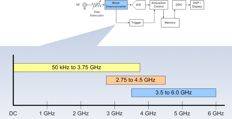
Consider the architecture of the RF spectrum analyzer front-end. Just beyond the input attenuator, the RF signal enters a block downconverter. This block conversion is used to translate the microwave frequency bands down below the Nyquist for the 10GS/s A/D in the RF path. The figure below shows a simplified block diagram of the RF path with the block downconverter highlighted. There are three bands of operation. The low band (50kHz to 3.75GHz) is essentially a pass-through straight to the A/D. The mid-band (2.75GHz to 4.5GHz) and the high-band (3.5GHz to 6GHz) perform wideband block downconversion for the signals in these frequency ranges. There is 1GHz of overlap between each of these blocks. This is what gives rise to the 1GHz minimum acquisition bandwidth of the MDO’s RF spectrum analyzer input. The center frequency and span selected by the user determines which conversion block is being used for the acquisition.

This figure shows a simplified block diagram of the RF path in the MDO4000. The highlighted block downconverter is used to translate the microwave frequency bands below the Nyquist frequency of the A/D.
This has implications on the RF power trigger signal which is essentially a broadband RF power detector that takes its input from the output of the block converter. In other words, the RF power detector “sees” the total RF power of the conversion block in use. The subtle, but important, concept here is that the frequency range seen by the RF power detector will often exceed the frequency range (span) observed on the spectrum analyzer. Therefore, it is possible that the RF power detector will see signals that are not observed on the spectrum analyzer display.
Consider the following example: The center frequency is set to 2.45GHz with a span of 100MHz, to observe signals in the popular 2.4GHz ISM band. The RF path uses the low-band block as shown in the figure above. This means the RF power trigger’s broadband RF power detector will be measuring the total RF in a frequency range of 50kHz to 3.75GHz. That’s a lot more frequency range than is shown on the 100MHz span on the analyzer. Thus, any signals that appear anywhere in this low-band frequency range that contribute to make the total power exceed the threshold set in the trigger settings will cause a trigger to occur. In other words, the trigger could be generated by a signal that is not visible in the spectrum analyzer display.
In most cases, this is not an issue since you’ll be in control of what signals you apply to the RF input, and therefore will know what frequencies will be present. However, where this can become an issue is when an antenna is used on the RF input without any type of filtering. Under these conditions, the antenna may pick up strong signals that are outside of the frequency span of interest and cause a trigger to occur. In the example above where the frequency range of interest is the 2.4GHz ISM band, it may be possible for the antenna to pick up cellular signals, 915MHz ISM band signals and UHF public service signals among others and send these all to the RF power detector in the trigger circuit and cause a trigger event to occur.