
Use the Keithley DMM 7510 to check out voltage and ripple to make sure you are within spec.
Prototyping is one of the more exciting steps in the design cycle. This is the stage where you ideally get to see your design vision spring to life – that is if everything goes according to plan. A lot can go wrong with board routing, solder joints, component placement and parasitics so when testing a prototype power supply it’s wise to proceed cautiously.
It is common practice but still worth mentioning that all input and output stages should be checked for short circuits using a digital multimeter. Do the same for all critical power points on the board to make sure none of the circuits are unintentionally shorted. Isolate the low-voltage analog and digital circuit into as many sub-circuits as possible. This will help with debugging problems and damage control if something goes south.
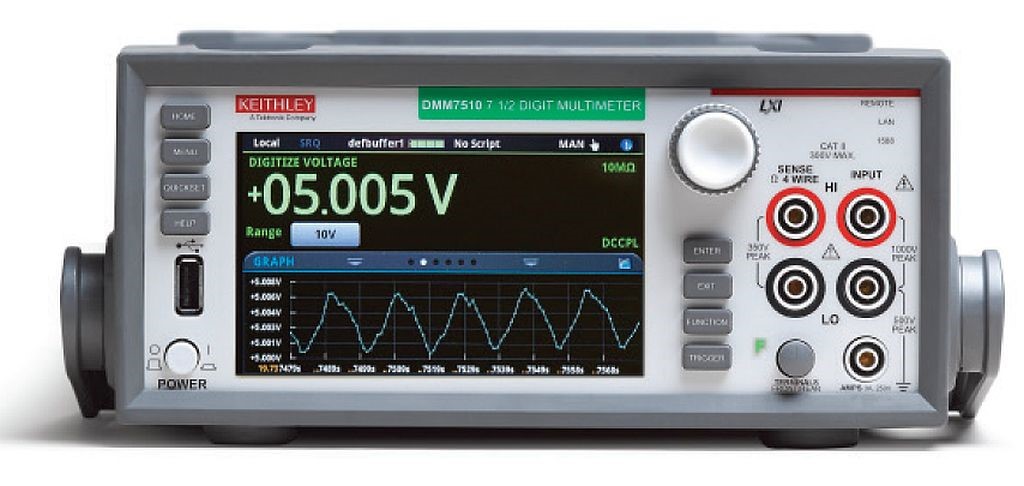
There is a good chance your design has at least one auxiliary power supply on board. The next step is to isolate this power supply and test the output with and without load. This will help characterize the power supply by itself and help isolate problems if any. Check out voltage and ripple using a precision multimeter such as the DMM 7510 (pictured above) and make sure everything is within specification. The DMM 7510’s graphical interface can also help you view high frequency ripple right on the screen. If you are interested in learning more about ripple measurements, here’s an appnote that walks you through a detailed process.
While the power supply is isolated, check all the low voltage circuits that the onboard power supply powers. Use an isolated DC power supply such as Keithley’s 2280S to power on the individual low-voltage sub circuits instead of the on-board supply. This will help isolate individual issues with sub circuits.
On the off-chance that the on-board power supply has multiple outputs, you can use a DC power source with multiple isolated channels. Use a DC power supply that shows the programmed settings and the actual measured outputs, simultaneously. This will enable you to see if the DC stages are drawing too much current. Your other option is to connect a DMM, such as a DMM 7510, between the power supply and the device under test to closely monitor current draw and power consumption. At this stage you should also test standby and state currents for each sub circuit if desired. Keithley’s 2280S Precision Measurement Power Supply with 10 nA resolution and at 0.05% accuracy can help with very low current testing common with modern high efficiency designs.

The Keithley 2280 power supply can help with very low current testing.
Lastly, if you need to provide a precise voltage to your system under test, consider using a 4-wire, remote sensing bench power supply. This device will eliminate the impact of any voltage drop in wiring between the bench power supply and your system during tests.
Next up, we’ll look at high-voltage AC circuit power-on.
Previously in the 10-part series:
Part 1: Component Selection and Characterization for Power Supply Design