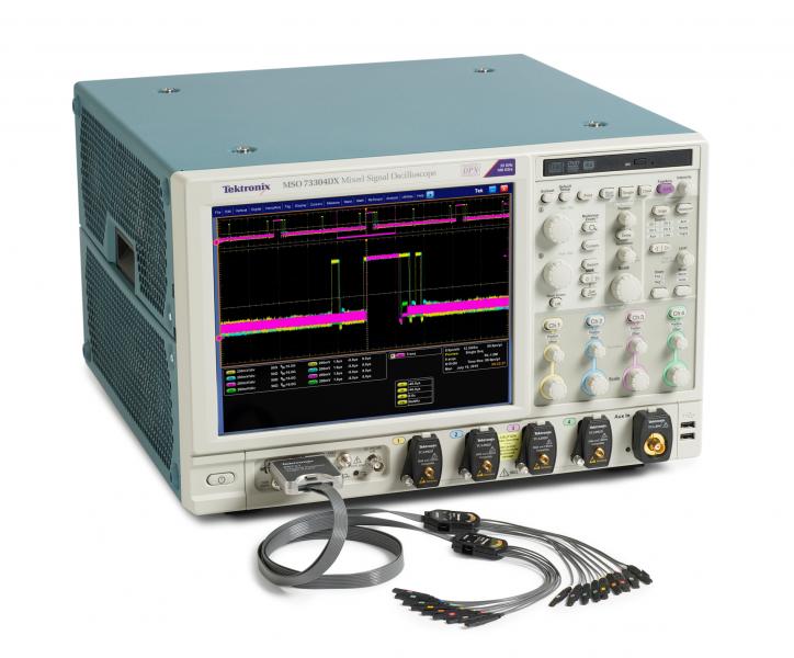

With last week’s introduction of the MSO70000DX Series, Tektronix has extended its performance mixed signal oscilloscope (MSO) series up to 33GHz on four analog channels coupled with 16 digital channels. This is a reflection of how important this product category is becoming to design engineers since the first performance MSO was introduced in 2009.
A performance MSO is defined by its analog bandwidth capabilities. With bandwidths exceeding 4GHz on the four analog channels and an impressive timing resolution of 80ps on the 16 digital channels, this class of MSO is able to address some very demanding test applications.
Over the past several years, engineers around the world have discovered many new applications for performance MSOs. Here are a few examples:
High-speed memory system validation: DDR (Double Data Rate) memory bus controller speeds are now exceeding 3 gigatransfers (GTs) per second in the latest DDR4 generation (JESD79-4) which brings an added level of timing validation requirements. Engineers have been adopting the MSO to perform this validation because of its broad system visibility and high signal fidelity. For analog validation of read/write cycles, three of an MSO’s analog channels acquire data from the Clock, Strobe (differential) and Data signals off the memory bus. In concert with that acquisition, the MSO’s digital channels capture data from the command/address bus to verify the timing integrity of this critical control link in a high-speed memory system.
This is particularly helpful in instances where the JEDEC specification is loose on the signal characteristics that define read and write cycles. In such cases, memory design engineers experience situations where their system appears to be within specification during analog validation, but internal algorithms do not catch the cycle correctly. Using the digital channels, the engineers are able to determine when valid data is on the control link and whether it is a read or a write.
Providing this broad system visibility is what a performance MSO is best suited for. Once data is acquired across the analog and digital channels and displayed on a common horizontal timing scale engineers are able to validate and debug with greater confidence.
Serial bus debugging: Many high-speed serial bus communications systems contain separate configuration and control channels that transmit at lower speeds but interact with the high-speed 8b/10b traffic containing the clock and data lanes. In some cases, signal integrity issues on the high-speed serial bus traffic can be debugged when the designer has a better understanding of the control bus which can be simultaneously acquired and viewed on a performance MSO.
Engineers working in the consumer electronics environment are familiar with HDMI’s signaling architecture which includes a DDC (Data Display Channel) bus used for operational control of the HDMI-based display transmission system. DDC is fundamentally an I2C protocol bus running at sub 100MHz speeds. With a performance MSO’s analog channels acquiring the clock and data from the >3 GHz HDMI signal lanes, the digital channels are used for acquiring the DDC bus and decoding the traffic on it.
That level of visibility could enable design teams to debug the DDC line and determine that DDC writes were going to the wrong address, for instance. With both analog and digital acquisitions running into the MSO’s memory, an engineer could perform trend analysis of the entire system’s data, to discover that the DDC line was writing the wrong address because the edge rates of the high-speed serial data were too fast. In one specific case, engineers at a consumer electronics company were able to debug the issue back to the cable shielding on their HDMI cable. Shielding was improved and the driver for the data was slowed to remedy the edge rate issues.
Frequency agile radio system control: Many of today’s modern radio designs deploy digital control channels which enable specific modulation effects for the radio’s output. This level of control needs to be validated in a radio’s system to ensure the timing of the correct frequency output. Performance MSO’s can be used to perform a frequency domain measurement on the radio’s output using Discrete Fourier Transforms (DFT’s) on the waveform data to construct spectrogram and spectrum-based views of an incoming wideband RF signal.
This analysis is performed on Tektronix MSO70000 Series using a software suite called SignalVu. The digital timing can be debugged using the incoming digital channels connected to the control bus of the radio. When the logic trigger on the MSO is set properly, the instrument can perform timing correlation of the logic state to the voltage spike appearing on the analog channel.
For advanced analysis of RF performance, Discrete Fourier Transforms (DFTs) are performed with SignalVu to show the spectrogram and spectrum frequency domain analysis, and time sampled data is displayed as RF I&Q vs. Time and Amplitude vs. Time. Time correlated markers from the digital channels of the MSO can be displayed in SignalVu to demonstrate the time-correlation of the RF analysis for debug using different views.
With the introduction of the MSO70000DX Series, Tektronix is meeting the growing demand for the power of an MSO for these and many other applications. For more information on the new MSO70000DX take a look at our product page or read up on news coverage in EDN, Evaluation Engineering, ECN or Design World among others.